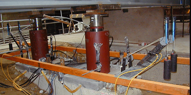
STATIC LOAD TESTS
The static pile load test or SPLT is the most common method for testing the capacity of a pile and it is also considered to be the best measure of foundation suitability to resist anticipated design loads.
Static tests are performed slowly which results in large displacements being recorded. This is because the shear strength of soil is loading rate dependent. Because of this mechanism, dynamic tests do not take static behaviour like creep and consolidation into account. Creep is an important consideration for all soil types and any form of rapidly loaded test will always distort ultimate load values.
Static pile load testing is the most definitive method for determining pile capacity and should be used to establish a correlation with dynamic test methods. If dynamic testing completely replaces static testing on a project, no correlation is established and signal matching relies on experience alone. This extra risk comes with an increased factor of safety over static testing plus correlated dynamic testing.
DATA ACQUISITION AND LOAD CONTROL SYSTEM
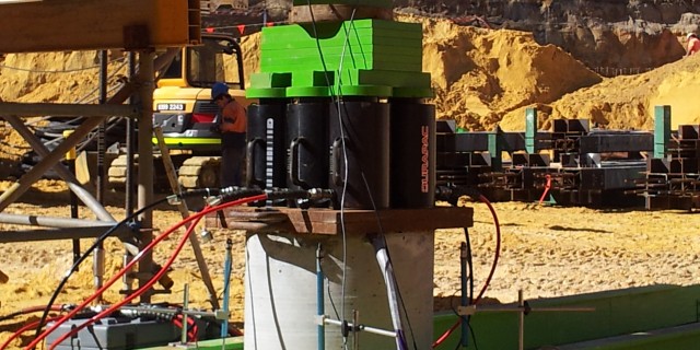
The pile load test is monitored electronically using a notebook computer based data acquisition system. Data can be recorded at sample rates of 10Hz, 1 Hz, 0.2Hz, 0.07Hz and 0.02Hz, depending on the rate of loading or events occurring.
Load is measured with a load cell placed between the hydraulic cylinder and the pile loading arrangement. A pressure transducer will monitor hydraulic cylinder pressure. Pile head travel is measured with four displacement transducers mounted from timber reference beams.
This image shows the 4 displacement sensors monitoring the travel of the pile head during the load cycle.
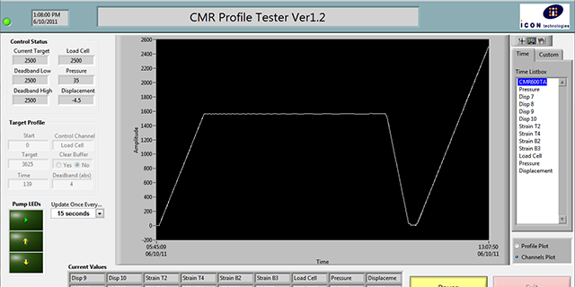
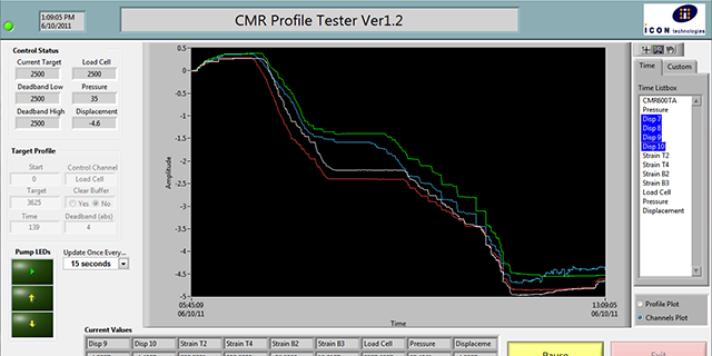
This image shows the screen graphics for the data acquisition software. The software gives the operator the ability to enter the load control parameters.
A target load and a time to reach the target is entered. Load is then controlled by the data acquisition computer using a solenoid valve control unit and electric pump. The software will use feedback from the load cell to control the hydraulic valve unit. The trace depicted is the output from the load cell against time.
The same data acquisition and control system is used for static compression tests, tension tests and lateral tests.
During the test the output from any sensor can be plotted against time or against another sensor. Load verses average displacement for instance. Other channels are available for strain or further displacements.
The data acquisition and control computer actuates the solenoid valve unit to adjust the hydraulic system pressure depending on the difference between actual load and the demand load. The generator for the system is also contained within the trailer.
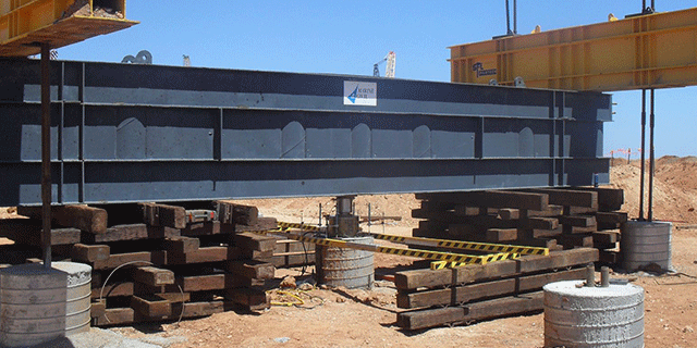
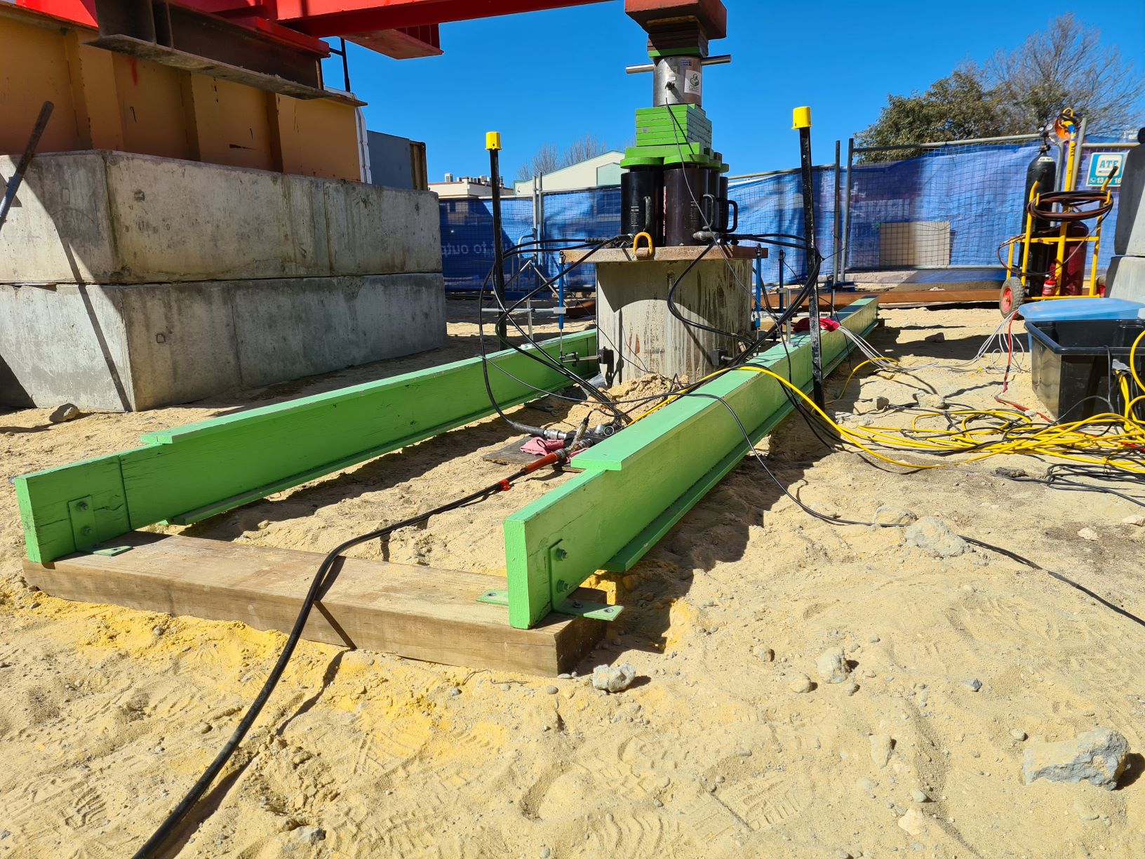
A CFA pile being loaded in compression. The pile also has strain gauges installed on the rebar cage. This will provide a stress profile down the length of the pile.
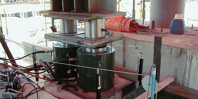
A high capacity bored pile being tested in compression. the pile has a weighted cable system to measure displacement down its length as well as the pile cap. The two load cells are summed to provide total load.
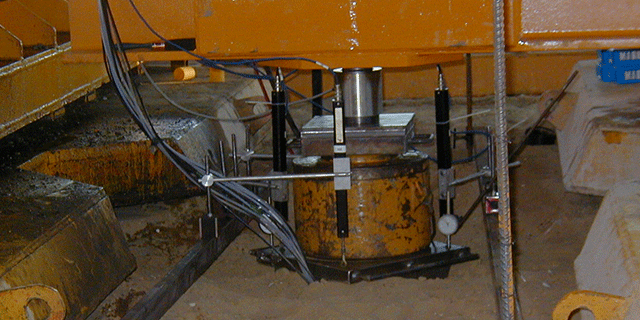
A precast pile that has been installed by jacking in. The rig used to install the piles is used as kentledge for the sustained load test. The pile has strain gauges embedded at intervals down the length of the pile.
